


3.0 Accessing the Device
3.0.1 Accessing the Device - Setup Wizard Page
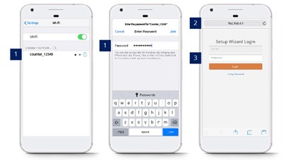
STEP 1 - Connect counter SSID via Wi-Fi and login with password: Please get from FFC support personnel..
STEP 2 - Access to web browser (Safari, Google Chrome) and enter URL: http://192.168.4.1.
STEP 3 - Login with password: Please get from FFC support personnel.
3.0.2 Reset Password - Setup Wizard Page
STEP 1 - Connect counter SSID via Wi-Fi and login with password: Please get from FFC support personnel..
STEP 2 - Access to web browser (Safari, Google Chrome) and enter URL: http://192.168.4.1.
STEP 3 - Click on Change Password and enter your preferred password.
STEP 4 - Complete the process and click on Save.
3.1 Basic Device Details
 |
 |
 |
Setup wizard Info
There are 5 tabs available in the drop-down menu located at the top left corner:

OPTION 1 - Navigate to the Live page.
OPTION 2 - Navigate to the Analytic page.
OPTION 3 - Navigate to the Validations page.
OPTION 4 - Navigate to the Config page.
OPTION 5 - Navigate to the Status page.
|
Page |
Description |
|
1. Live |
Able to check on the live video stream |
|
2. Analytic |
Not available yet |
|
3. Validations |
Not available yet |
|
4. Config |
Configure the IT details and enter the pairing code. |
|
5. Status |
Displays the current device status, including connection status. |
Live Page Setting
There are 3 options for the liveview:
Video Stream - Show device live stream.
Static Images - Show static image of the device liveview
No Images - No show any live stream or image
Config Page Setting
This is the page to set the IT details for the device:
Counting - Show device live stream.
Network - Show static image of the device liveview
System - No show any live stream or image
Log - No show any live stream or image
|
Tab |
Description |
|
Counting |
User can set the mounting height here, also can set the counting method here such as Group Counting, Child Counting, and etc |
|
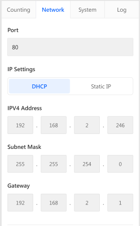
Network |
User can set the IP setting here, such as the IPV4 Address, Subnet Mask and Gateway. |
|
System |
User can enter the site pairing code here to allocate the device to the site. |
|
Log |
User can review the changes that had been made in this log |
Status Page Setting
User will be able to check the device status here:
Device Setup Status - This is important as it will state the status of the device.
|
Device Setup Status |
Description |
|
1. Not Paired |
Network connected, Server connected, Device not having a pairing code OR not paired yet. |
|
2. Connected to Analytics Server |
Network connected, Server connected, Device Pairing successful. |
|
3. DHCP is Not Reachable |
DHCP server checking failed. Can't grab the gateway / IP address. |
|
4. IP is Out of Range |
Intended to use a subnet mask and gateway to obtain the range of IP addresses. The error will occur if out of range. |
|
5. DNS Lookup Failed |
Rule: Intended to resolve the server address using DNS that is filled in by the user. The error will occur if the DNS fails to resolve the server address. |
|
6. Proxy is Not Reachable |
Rule: Proxy is set but not able to access our Server Network Issue. Analytics Server not reachable will also cause this issue. |
|
7. Server is Not Reachable |
The network is connected; the Server is not connected. Rule: Not able to ping (client) server or FFC server. |
|
8. Eth0 is Not Enabled |
Rule: Failed to obtain information on ethernet cable connected to the counter. Constant yellow light is most likely related to cable issues. Normally due to a faulty cable/cable not being crimped correctly or a connection between ports not plugged firmly. |
|
|
|
3.2 Device Network Setting
3.2.1 Updating IP setting network
When users want to change their IP settings on their corporate network, the IP details inputted on the FootfallCam device must be updated as well. If the IP details is not updated on the FootfallCam counter prior to the change of the corporate IP network settings, the counter will not be able to upload visitor counting data to the FootfallCam Analytic Manager.
-
Access to the device. See 3.0.1 Accessing the device
-
Update the IP setting
Once the user has access into the FootfallCam device, the user will need to overwrite the existing IP detail with their new setting.
-
The user will need to navigate to the Network tab on the bottom of the Config page.
-
Select the option Static IP.
-
Once the user has inputted the new IP settings, click Save to update the settings.
-
When the new IP setting is applied, the FootfallCam device will appear as offline due to unmatched IP setting between the device and the corporate network.
-
-
Update internal network settings
Once the FootfallCam device has been configured for the new IP setting, the FootfallCam will appear as offline and will be unavailable for remote access. The user can then configure their corporate IP settings to match the settings inputted into the FootfallCam device.
3.2.2 Redirecting the server address
When users would like to use a new server for data access from the FootfallCam, the FootfallCam device manager must be logged in onsite to update the new server address. Once the server address is updated, the device must be re-allocated on the new server prior to data display.
- Access to the device. See 3.0.1 Accessing the device
-
Update the server address - Once the user has access into the FootfallCam device, the user will need to overwrite the existing server address with the new detail.

-
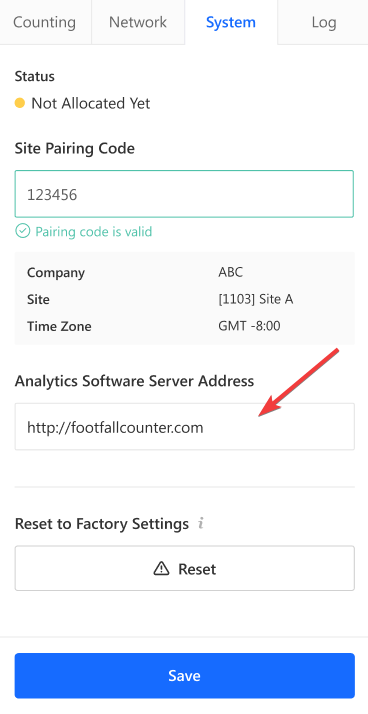
The user will need to navigate to the System tab on the bottom of the Config page.
-
Under the option Analytics Software Server Address, enter the desired address of the new server where data will be streamed to. To use FootfallCam cloud server, please enter http://footfallcounter.com.
-
Once the server address is updated, Reboot the counter.
-
3.3 Device Pairing
In order to pair the devices with the installed site, engineer MUST enter the paring code for the specific site shared by the customer on every devices installed. Otherwise, the data collected by the devices would not able to send to the server for the reporting purpose.
Pairing code is unique for all site(s). Please refer to Section 4.1.1 Share Pairing Code.
3.4 Basic Tuning
STEP 1 - Access to Setup Wizard page
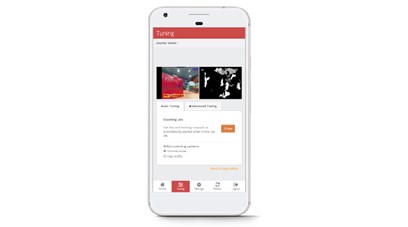
STEP 2 - Click on Tuning tab.
STEP 3 - Click on Draw in Basic Tuning tab.
STEP 4 - Complete the process by drawing line and click on OK to apply the changes.
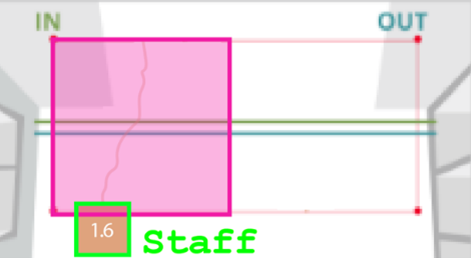
3.4.2 Staff Exclusion Kit
Staff exclusion kit is an additional peripheral attached to the counter internal chipset accompanied by a remote button. User require to press the remote button within the Staff Exclusion Zone for excluding the counting of staff. Two (2) outcomes will be trigger once the remote button is pressed are listed as below:
OUTCOME 1 - LED light on counter will blink 3 (three) times in Red colour and remain in Red colour for 5 seconds to indicate that the staff has been excluded.
OUTCOME 2 - LED light on counter will blink 3 (three) times in Red colour before reverting to original colour.
 |
 |
 |
|
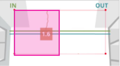
Staff requires to press the remote button within the exclusion zone (pink). |
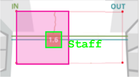
Staff will automatically be detected as staff. |
Staff can proceed to walk through the entrance as usual. |
|
Option 1 - Automated Setup |
|
STEP 1 - Access to the device. See Section 3.0.1: Accessing the device STEP 2 - Navigate to counter live view and ensure that no individual stand underneath the view of counter. STEP 3 -User may stand underneath the view of counter and press the remote button for 5 seconds. |
|
Option 2 - Manual Setup |
|
STEP 1 - Access to the device. See Section 3.0.1: Accessing the device STEP 2 - Click on Tuning tab and follow by Basic Tuning tab. STEP 3- Click on Draw to indicate a minimum of three (3) points on the live view. STEP 4 - Complete the process by drawing line and click on OK to apply the changes. |
3.5 Walk Test
Initiate a walk test after installing the counter at the site. The walk test varies between 2 minutes to 15 minutes with at least 20 IN and 20 OUT and the time can be adjusted based on your preference.
The purpose of doing the walk test during the installation:
1) This is useful to collect sufficient sample size for faster and better verification.
-all the possible pathways can be tracked from the device
-to speed up the verification process by using the walk test sample (some stores might have a really low
sample from the scheduled video)
2) To ensure all the add-on features can work properly (e.g staff exclusion tags, staff exclusion button)
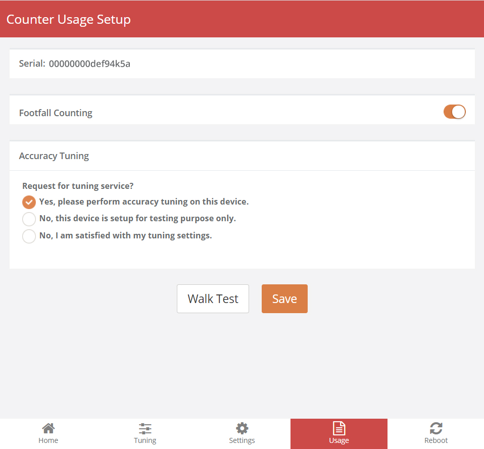
STEP 1 - Navigate to the tab Usage, click on Walk Test to start recording a video.

STEP 2 - After choosing the video duration between 2 minutes to 15 minutes, proceed to click confirm.
STEP 3 - Walk all possible ways that a normal visitors would enter the premise.
STEP 4 - A head tracker should appear on the person.
STEP 5 - Counts will be triggered when the person crossed the INOUT lines.
STEP 6 - Once the video has finished recording, there will be a green tick appear to notify. The video is uploaded to server for FootfallCam Specialist to fine tune the settings.
You may also assess the link below for the way to self-record walk test guide: