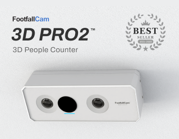
IoT devices such as FootfallCamTM 3D Mini, FootfallCamTM Space Sense, etc. do not have direct connection to Analytic Manager V9. These IoT devices need to be bound to a transmitter (e.g. FootfallCamTM Mesh Hub) in order to push the data to server.
1.1 Pre-requisite
Before binding the IoT devices, the transmitter need to be paired to a site first (please refer here on how to pair a device to site). This is to ensure the data collected by the IoT devices can be uploaded to the server under the site paired.
1.2 Binding of IoT Devices to the Transmitter
STEP 1 - Search for the transmitter's Wi-Fi SSID and connect.
STEP 2 - Login in the Device Setup Wizard Page. (Please get the password from FootfallCam support personnel)
STEP 3 - Access to web browser (Safari, Google Chrome) and open the Sensor Nodes Pairing with the IP Address. (Please get the IP Address from FootfallCam support personnel)
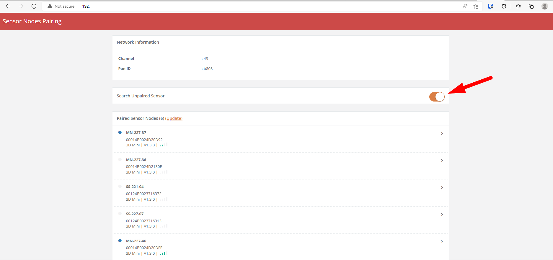
STEP 4 - Turn on the Search Unpaired Sensor button to search for the IoT device(s) nearby. (It may takes up 1 minutes to search)
1.3 Unbind IoT Devices
1.3.1 FootfallCamTM Space Sense
STEP 1 - Unscrew the Space Sense
STEP 2 - Hold the button until the LED light is blinking fast
STEP 3 - Power cycle the Space Sense
1.4 Update Basic Sensor Information
STEP 1 - After the IoT device is bound successfully, tap on the IoT device (under 'Paired Sensor Nodes' section) to configure the settings.
STEP 2 - View and update the basic information.
|
Item |
Description |
|
1. Device name |
Enter your preferred name for the device. |
|
2. Status |
Display the connection status of the device. |
|
3. Serial |
Display the serial number of the device. |
|
4. Model |
Display the model of the device. |
|
5. Signal Strength |
Display the signal strength of the device. |
|
6. Firmware |
Display the firmware version of the device. |
1.5 Configure Tuning Settings for IoT Devices
1.5.1 FootfallCamTM 3D Mini
STEP 1 - After the 3D Mini is bound successfully, tap on the 3D Mini (under 'Paired Sensor Nodes' section) to configure the settings.
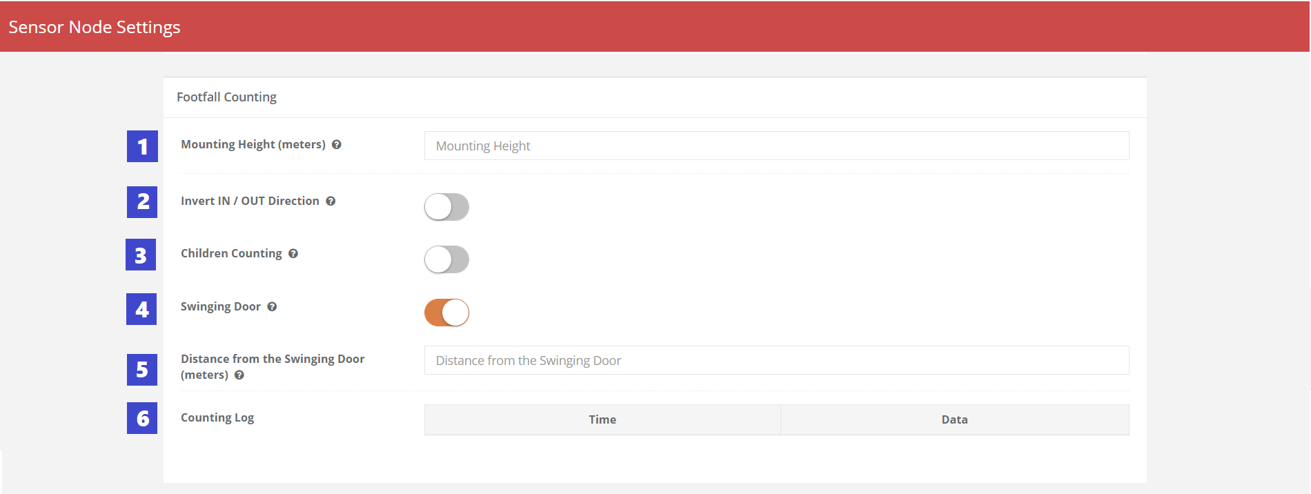
STEP 2 - Configure the tuning parameter settings and Save.
|
Item |
Description |
|
1. Mounting Height (meters) |
Enter the height between sensor and floor. |
|
2. Invert IN / OUT Direction |
To invert the IN / OUT direction for the footfall counting data. |
|
3. Children Counting |
To enable children (with height lower than 120cm) to be counted by the sensors. |
|
4. Swinging Door |
To indicate there is swinging door and to eliminate the door to be counted as footfall. |
|
5. Distance from the Swinging Door (meters) |
Enter the height between sensor and top of the swinging door. |
|
6. Counting Log |
Display the records of the IN / OUT counting of the latest time. |
STEP 3 - Perform walk test (walk in and out the entrance where the device is mounted for a few times) and see if the IN and OUT data is logged in Counting Log [point 6 in the image above] . If the data logged is not match with the actual IN and OUT direction, you may toggle the Invert IN / OUT Direction button [point 2 in the image above].
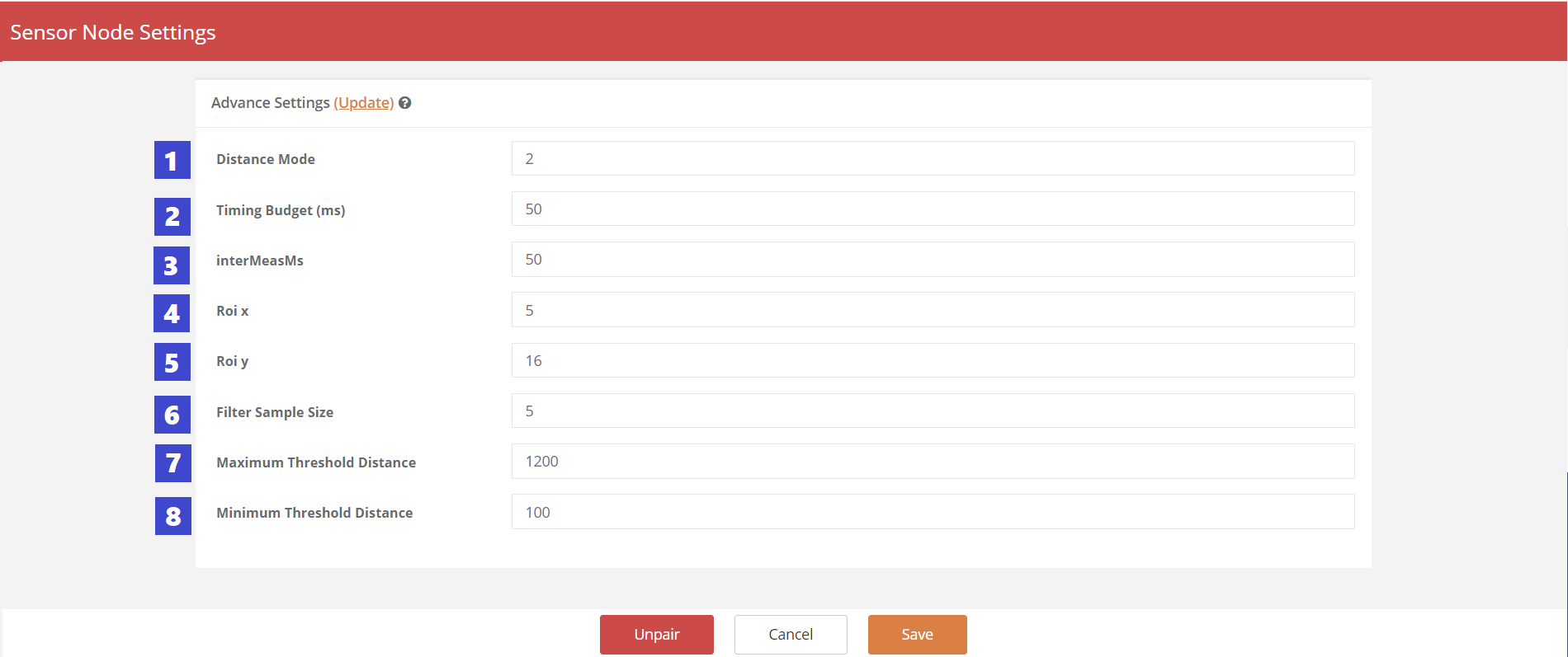
STEP 4 - Advance tuning is required if the basic footfall counting setting is not sufficient to provide accurate counting. Please contact FootfallCam team to assist for Advance Tuning.
You required to briefly describe the situation of inaccurate counting of the 3D Mini, and send the print screen of the updated Advance Settings to FootfallCam team for advice.
|
Item |
Description |
| 1. Distance Mode | Short range or long range. |
| 2. Timing Budget (ms) | Get the value in the timing. |
| 3. InterMeasMs | Process the value that got in the timing. |
| 4. Roi x / Roi y | Area size of the detection in X-axis and Y-axis |
| 5. Filter Sample Size | Filter the data value that got to make sure to get the accurate data. |
| 6. Maximum Threshold Distance | The maximum of the distance that will be counted. |
| 7. Minimum Threshold Distance | The minimum of the distance that will be start counted. |
1.5.2 FootfallCamTM Space Sense
STEP 1 - After the Space Sense is bound successfully, tap on the Space Sense (under 'Paired Sensor Nodes' section) to configure the settings.
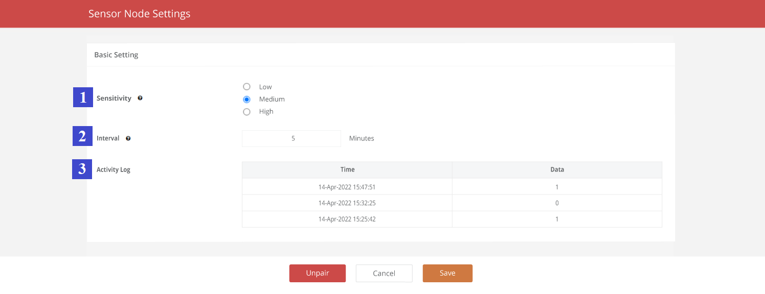
STEP 2 - Configure the tuning parameter settings and Save.
|
Item |
Description |
| 1. Sensitivity | The sensitivity toward movement for state change. Low sensitivity required bigger movement to detect the space is occupied while high sensitivity will trigger state change with smaller movement. |
| 2. Interval | The min. continuous time required of staying in the same state in order to trigger state change. Eg. If the interval is set as 3 minutes, the space need to be occupied for 3 minutes continuously to trigger the state change to "occupied", and vice versa. Minimum interval is 1 minute. Suggestion: The optimum interval will be between 2 minutes to 5 minutes. |
| 3. Activity Log | Display the state change detected by the space sense according to sensitivity and interval set. |
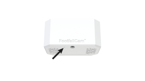
1.6 LED Light Indicators
 |
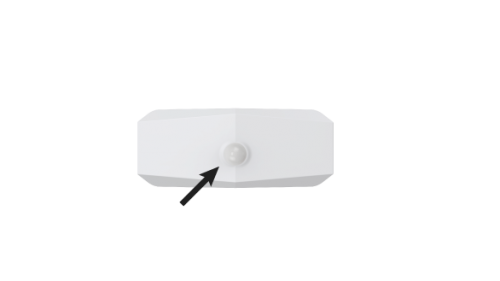 |
| FootfallcamTM 3D Mini | FootfallCamTM Space Sense |
|
LED Colour
|
Indication |
|
|
Wired Device |
Battery Device |
|
|
1. Constant Light |
(Ready) Bound Successfully and No Issue The device is bound to master device. |
N/A Note: Constant light will not be applicable for battery-powered device to minimize battery consumption |
|
2. Blinking Light |
(Not Ready) Pending for Binding to Transmitter > Condition: The device does not bind to any transmitter yet and wait for binding. > Action: Proceed to binding this IoT device to the transmitter. |
(Not Ready) Pending for Binding to Transmitter > Condition: The device does not bind to any transmitter yet and wait for binding. > Action: Proceed to binding this IoT device to the transmitter. |
|
3. No Light
|
(Not Ready) Not Power Up > Condition: Device is not powered up. > Action: Check the power supply of the IoT device.
|
(Not Ready) Not Power Up > Condition: If the Connection Status is Disconnected and No Light |
|
(Ready) Bound Successfully and No Issue > If the Connection Status is Connected and No Light
|
||

